project
Audio Amplifier Circuit
EE210 Fall 2024
Introduction
System Objectives
| Block | Function | Key Range / Thresholds | Core Parts |
|---|---|---|---|
| 1 Mixer | Stereo → mono summing, per‑channel trim | In: 0.025–1.0 Vpp ea. Out: ~0.01–0.04 Vpp nominal | Op‑amp, 2× 20 kΩ pots |
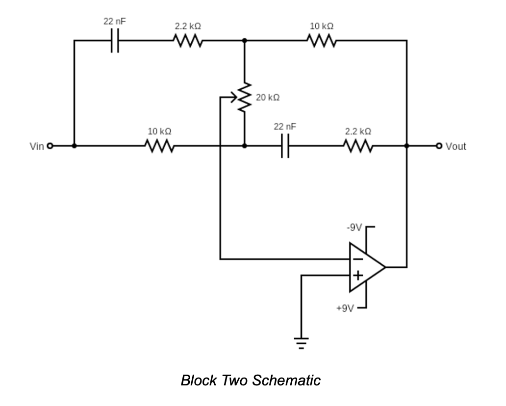
| 2 Tone | Adjustable bass / treble tilt | Gain LF 1/3×→3× (HF inversely 3×→1/3×), 20 Hz–20 kHz | RC network + pot |
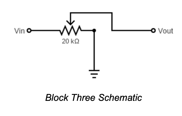
| 3 Volume | Post‑EQ amplitude control | 0 → ~1.2 Vpp | 20 kΩ pot divider |
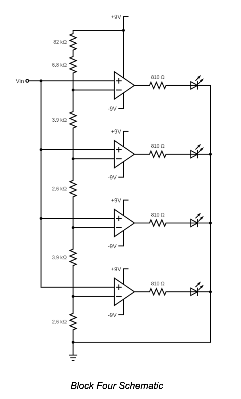
| 4 LED VU | Amplitude visualization | Comparators at 20 / 60 / 80 / 120 mV | 4 refs + LEDs |
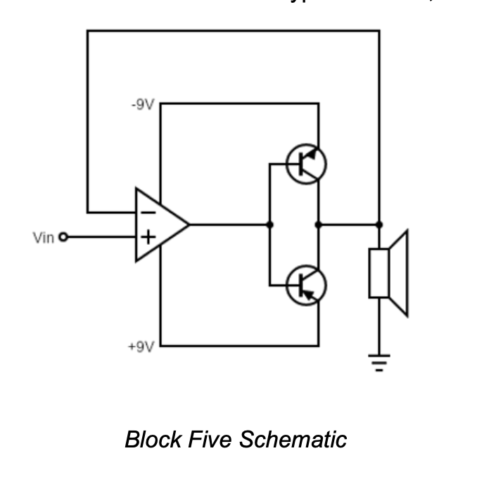
| 5 Power Amp | Current drive to speaker | Fixed gain, drives low‑Z load | TIP31 / TIP32 pair |
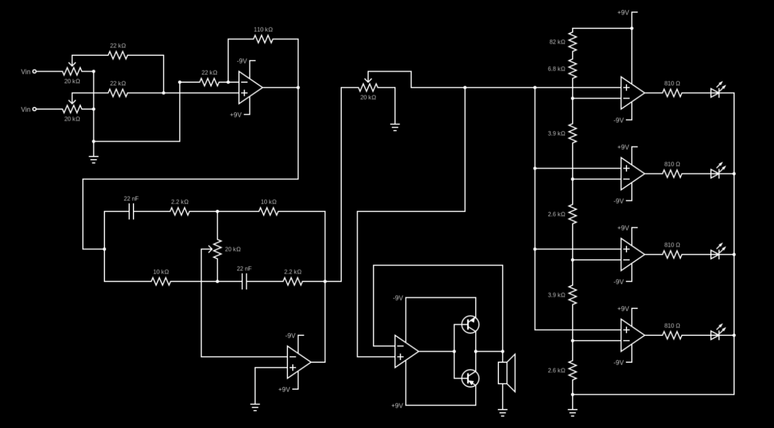
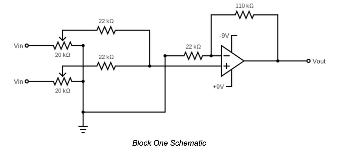
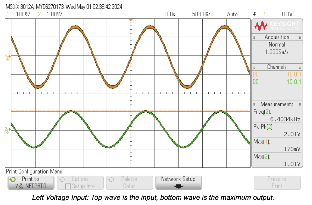
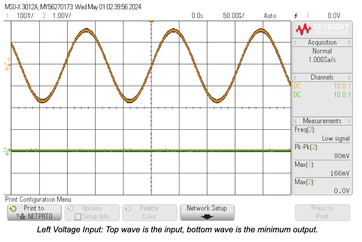
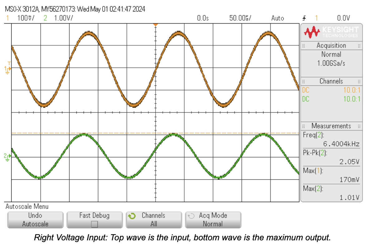
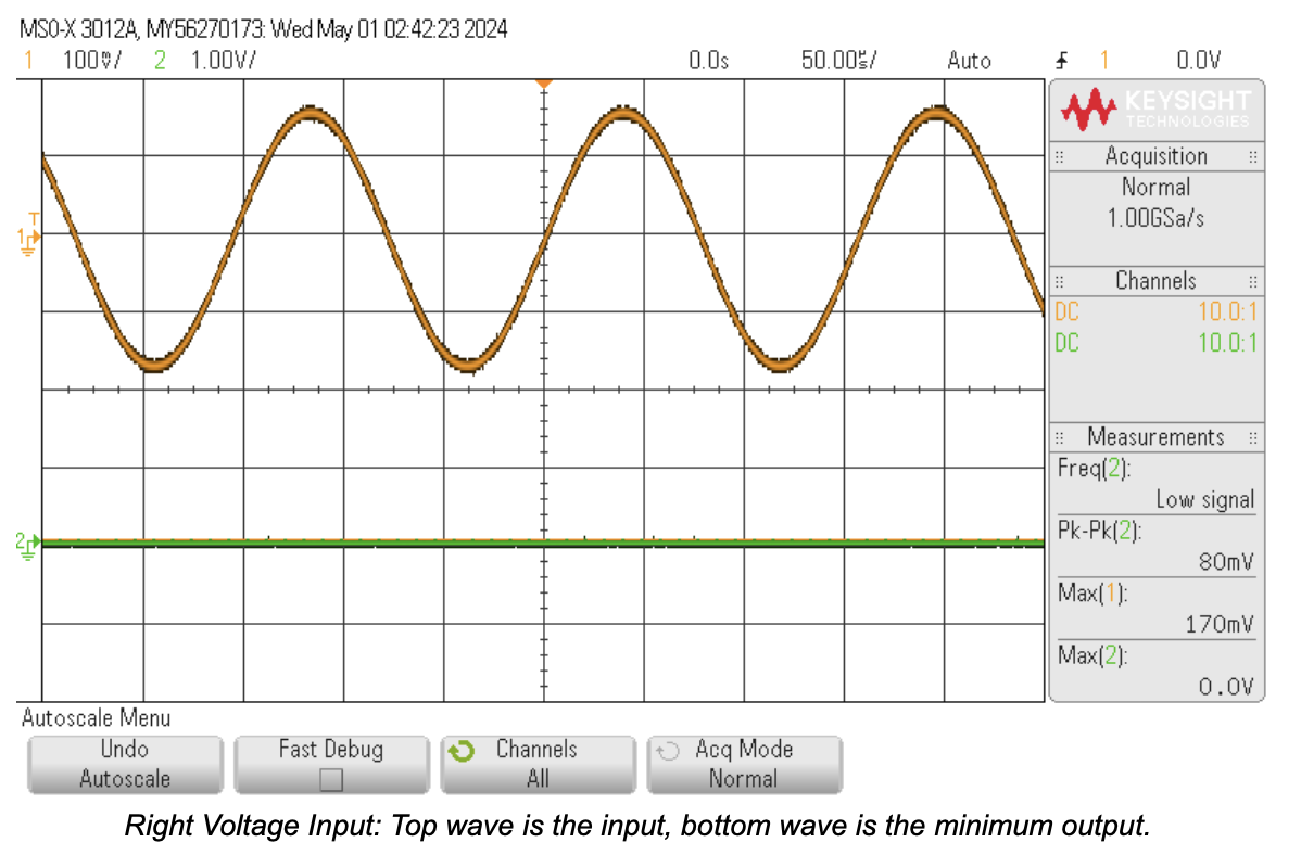
- Block 1 – Summing Mixer. Two AC‑coupled stereo channels feed an inverting summing node. Independent 20 kΩ potentiometers set per‑channel contribution without clipping the combined headroom (target mono output ~0.01–0.04 Vpp for nominal sources).
- Block 2 – Tone Filter. A single potentiometer sweeps a tilt‑style RC network: low frequencies can be boosted up to 3× while highs attenuate to 1/3× (or vice‑versa), covering the 20 Hz–20 kHz band with smooth spectral shaping.
- Block 3 – Volume Control. A 20 kΩ divider implements user gain from mute (≈0 Vpp) to ≈1.2 Vpp while presenting a low source impedance to downstream comparator and driver stages.
- Block 4 – LED Level Indicator. Four comparators reference a 9 V ladder (≈20, 60, 80, 120 mV). Progressive LED illumination forms a simple pseudo‑VU display without loading the audio path.
- Block 5 – Power Amplifier. Complementary emitter follower (TIP31/TIP32) supplies current gain; the op‑amp front end biases the pair to limit crossover distortion and cleanly drive the speaker at listening levels.
Theory & Experimental Methods
Theoretical Overview
- Block 1 (Summing Mixer): Implements an inverting summer. For equal input resistors Rin and feedback resistor Rf, each channel contribution ≈ −(Rf/Rin)·VCH. Potentiometers precede the summing node providing variable effective Rin (amplitude trim) to keep summed Vout within the 0.01–0.04 Vpp design envelope.
- Block 2 (Tone Filter): A single‑pot “tilt” network whose impedance division versus frequency alters relative LF/HF gains. At one extreme GLF ≈ 3×, GHF ≈ 1/3×; reversed at the other. Capacitor reactances chosen so pivot occurs inside the audio band (order of a few kHz) while still spanning 20 Hz–20 kHz.
- Block 3 (Volume Divider): Passive 20 kΩ potentiometer forming a variable attenuator with low output impedance ( ≪ comparator input impedance ), preserving tone shaping while setting 0–1.2 Vpp user level.
- Block 4 (LED VU Ladder): Resistor ladder establishes monotonic DC thresholds (≈20/60/80/120 mV). Each comparator outputs a logic‑level drive through its series LED resistor (~810 Ω) giving stepped amplitude indication. Instantaneous (no envelope) response intentionally chosen for simplicity.
- Block 5 (Power Stage): Complementary emitter follower provides current gain (β aggregation) without additional voltage gain; op‑amp supplies drive and bias to minimize crossover distortion while keeping the driver within linear output swing for the target speaker load.
Design Process
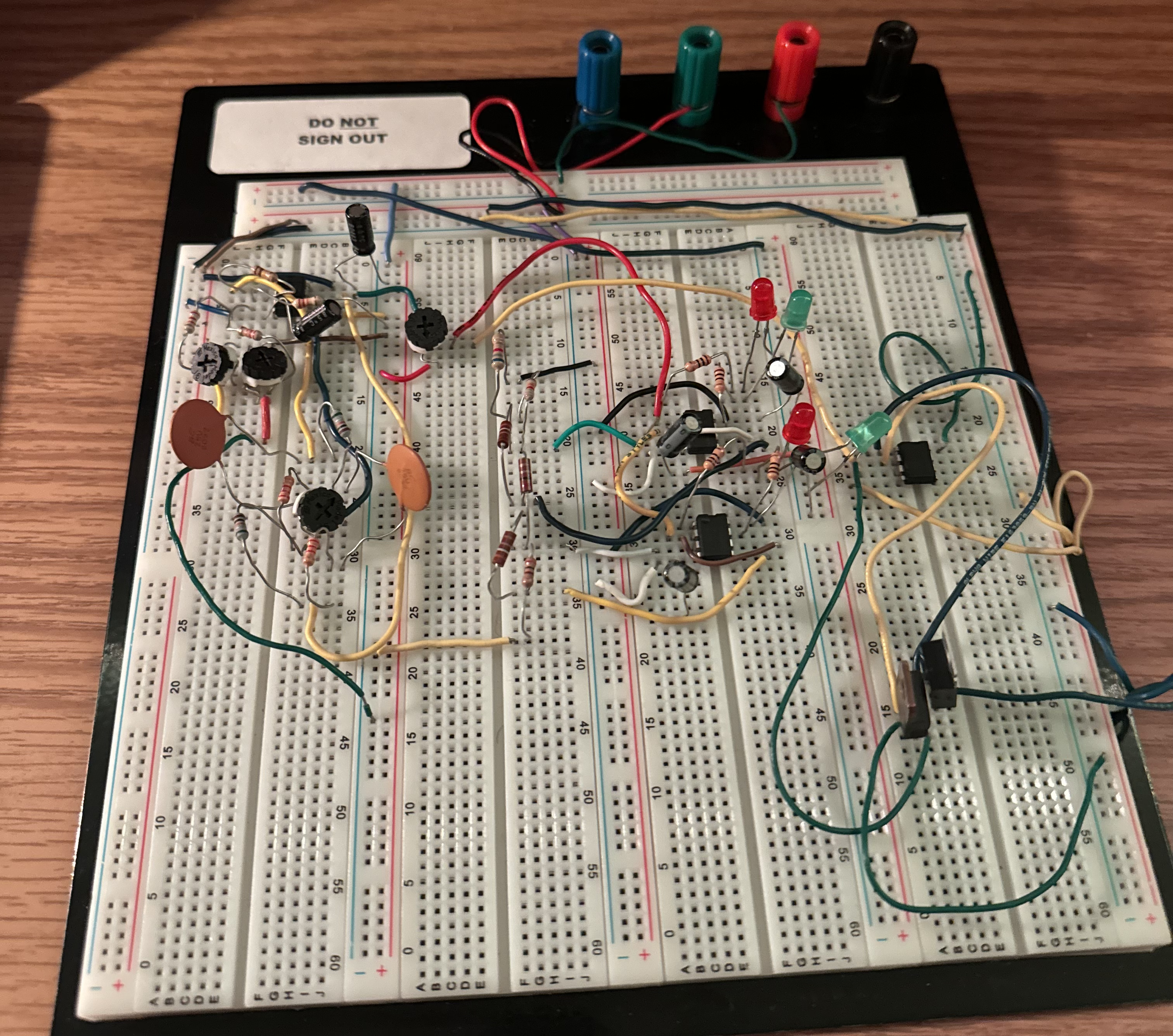
Blocks 1–5 Implementation
Compact gallery of the five functional stages. Click any card for details.
Details
A classic inverting summing amplifier mixes left/right into mono. Input potentiometers trim each channel to preserve headroom and minimize noise at the summing node.
Details
Potentiometer‑controlled RC tilt network shapes the spectrum (≈20 Hz–20 kHz) providing complementary bass boost vs. treble cut (and vice‑versa) without clipping.
Details
20 kΩ potentiometer as a divider provides smooth attenuation from mute to ≈1.2 Vpp while presenting low source impedance to comparators and driver.
Details
Four comparators reference a resistor ladder (~20/60/80/120 mV) lighting LEDs progressively for instantaneous amplitude visualization.
Details
Complementary TIP31/TIP32 emitter follower furnishes current gain; op‑amp front‑end biases the pair to limit crossover distortion and cleanly drive the load.
Results
- Stereo signals were mixed into a stable mono channel.
- Tone control produced clear bass and treble adjustments.
- The volume control stage provided smooth, reliable output scaling.
- The LED indicator responded dynamically to signal amplitude, creating a real-time visual representation of the music.
- The amplifier stage drove the speaker effectively at normal listening levels.
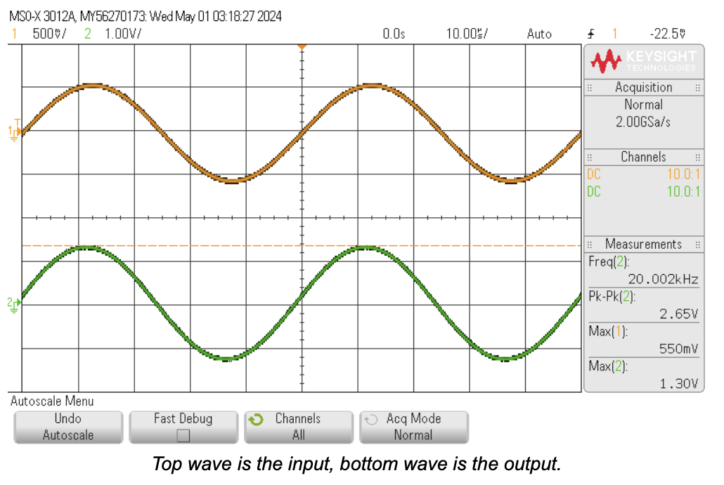
Oscilloscope Results
Each block was verified by capturing input (reference) and output waveforms. Use consistent vertical scaling so amplitude changes and threshold activations are visually comparable. Replace the src attributes below with your final PNGs/JPGs (recommended width 1000–1400 px for clarity). Keep captions concise and emphasize what changed between traces (gain, attenuation, threshold crossings).
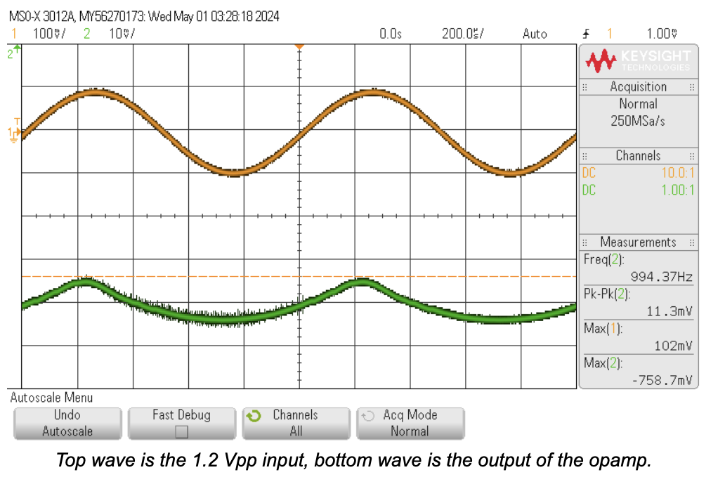
Block 1 – Summing Mixer (Independent Channel Trim)
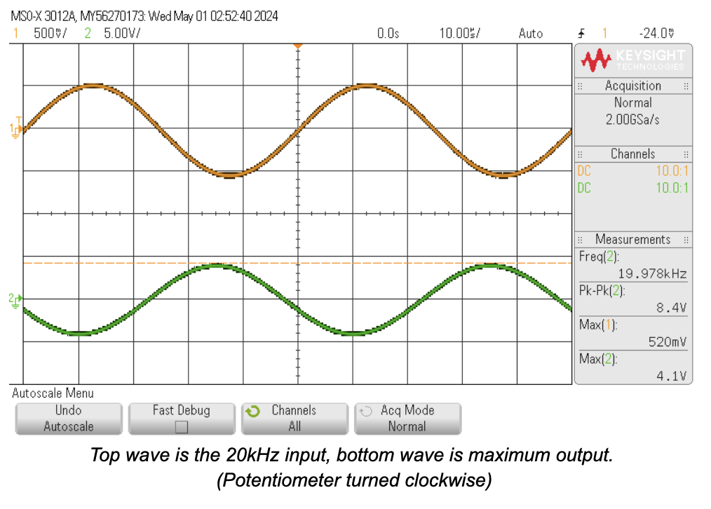
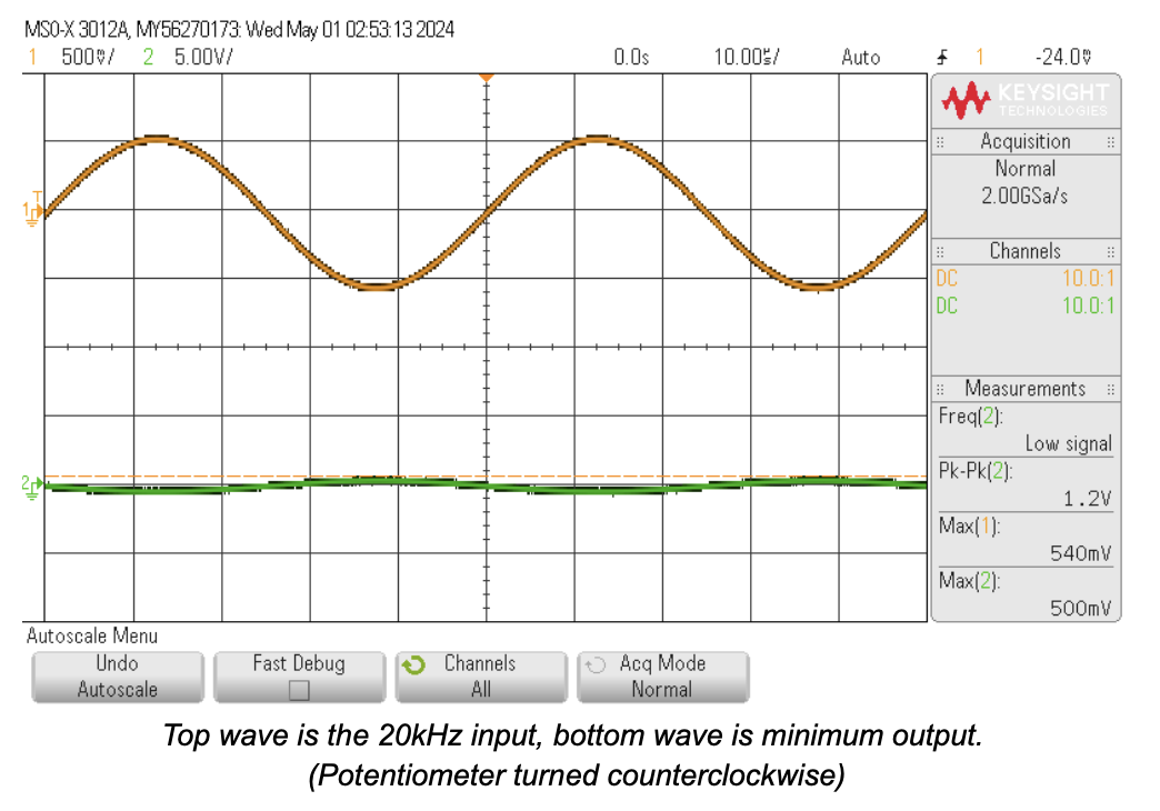
Block 2 – Tone Control (Tilt Extremes at 20 kHz)
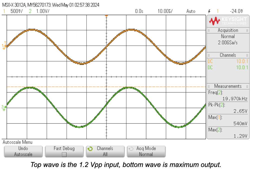
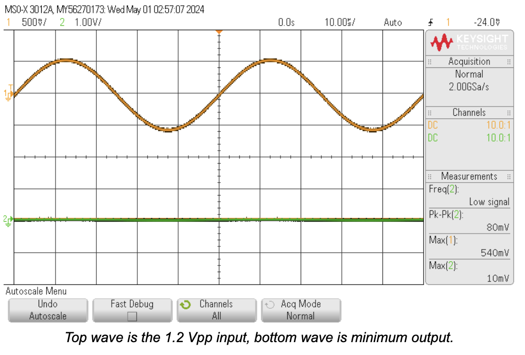
Block 3 – Volume Stage (Max vs Near‑Mute)
Block 4 – LED Indicator (Comparator Threshold Region)
Block 5 – Power Stage (Drive Integrity)