project
Pipelined MIPS CPU (5‑stage)
CMPEN 331 • Fall 2024
A 32‑bit pipelined MIPS processor with hazards resolved via forwarding & stalls.
Overview
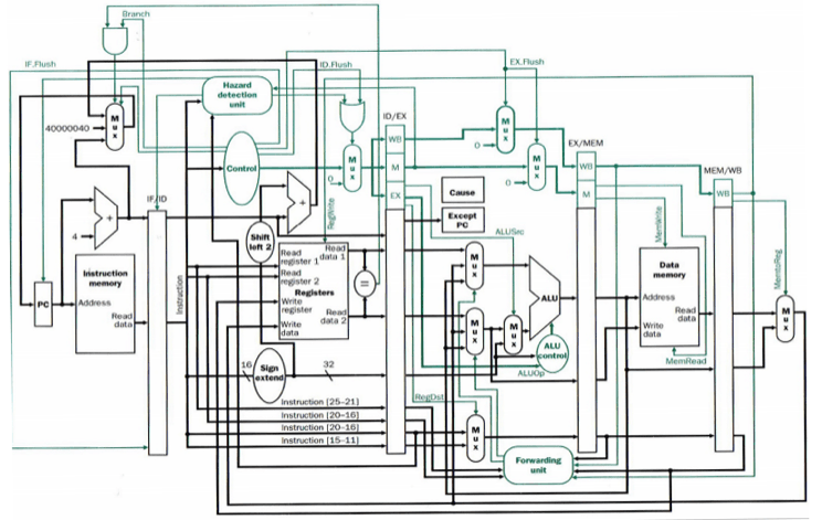
I built a small computer processor. It runs in five staged steps and can process multiple instructions at the same time. Formally, it is a 32‑bit MIPS‑style CPU implemented in Verilog with the classic five‑stage pipeline (IF, ID, EX, MEM, WB). Correctness and throughput are maintained by a hazard detection unit that inserts stalls when required and a forwarding network that supplies the most recent values to the ALU inputs.
Highlights
- Five‑stage pipeline: IF → ID → EX → MEM → WB
- Data forwarding on both ALU operands (EX/MEM and MEM/WB sources)
- Load‑use hazard detection with single‑cycle stall insertion
- 32‑bit datapath and register file (2R/1W), negative‑edge write timing
- Instruction subset: R‑type add/sub,
lw,sw - Modular Verilog design with clear pipeline registers and control separation
Microarchitecture
pc_adder advances the PC by 4.rs and rt; immediates are sign‑extended.Hazard handling
| Hazard | Condition | Resolution |
|---|---|---|
| EX data | Producer in MEM/WB, consumer in EX | Forward via forward_reg (select EX/MEM or MEM/WB result) |
| Load‑use | lw in EX, dependent consumer in ID |
hazard_reg asserts stall, inserts 1 bubble |
| RF timing | Read/Write same cycle | RF writes on negedge; reads are combinational |
Pipeline timing example
A short trace showing a single‑cycle stall on a load‑use dependency followed by forwarding:
| Instr | 1 | 2 | 3 | 4 | 5 | 6 | 7 |
|---|---|---|---|---|---|---|---|
| I1: lw r1, 0(r2) | IF | ID | EX | MEM | WB | ||
| I2: add r3, r1, r4 | IF | ID | STALL | EX* | MEM | WB | |
| I3: sw r3, 4(r5) | IF | ID | EX* | MEM | WB |
EX* indicates operands supplied via forwarding (from MEM/WB or EX/MEM as appropriate).
Correctness and performance mechanisms
- Data hazards: The
forward_regunit selects among ID/EX operands, MEM results, or WB results for each ALU input (forwardA and forwardB), ensuring the ALU receives the most recent values. - Load‑use hazards: The
hazard_regunit assertsstallwhen an instruction in EX is a load and the following instruction requires the loaded value in the next cycle. - Register file timing: Writes occur on the negative clock edge and reads are combinational to avoid read‑write conflicts within a cycle.
Design decisions
- Pipeline registers carry only the fields needed by downstream stages, minimizing fan‑out and simplifying control.
- Forwarding muxes are 3‑way (ID/EX, EX/MEM, MEM/WB), eliminating unnecessary bubbles for ALU‑ALU dependencies.
- Single‑cycle data memory keeps the MEM stage simple;
lwis the only case that forces a bubble on immediate use.
Architectural components
- Pipeline registers:
if_id,id_ex,ex_mem,mem_wb - Instruction set slice: R‑type add/sub,
lw,sw - Modules:
program_counter,pc_adder,inst_mem,register_file,control_unit,imm_extend,alu,data_mem, muxes (2×1, 3×1) - Verification: Simulated with a small instruction/data memory; waveforms confirm forwarding decisions and stall timing.
Example execution
The bundled program sequence loads two words, performs an addition, and introduces a dependent load to exercise a single‑cycle stall followed by forwarding. The waveforms illustrate the asserted stall and the subsequent selection of forwarded operands.
Source code
The complete Verilog source is available below. No files download automatically; use the provided buttons to access the material.