The Esotaira Tilt Propulsion project focuses on developing a 180° tilt mechanism that enables UAVs to transition between traditional and omnidirectional flight. The final system integrates high precision mechanical components with real time firmware to ensure stable and accurate control under active thrust.
Team
Sponsors & Advisors
Mechanical Design⌄
The mechanical goal of this project was to build a rigid tilting assembly that stays stable while the motors are running at high speeds. While the full UAV concept utilizes 12 propellers, our team was specifically responsible for the four central modules that provide the primary 0–180° tilt range for omnidirectional maneuvering.
Module Construction & Materials — To keep the design lightweight but strong, we used Onyx 3D-printed parts (carbon-fiber reinforced nylon). My role involved the fitting and finishing of these printed components to ensure the gears moved smoothly. Each module was built to be completely modular and met the strict weight requirement of under 0.50 lb per unit.
Safety & Testing Enclosure — Because we were testing live high-speed propellers, we built a custom Testing Box to keep the team safe. The enclosure features a solid wood base and walls made of epoxy-glass sheets, which are incredibly impact-resistant and clear for easy observation. This rig allowed us to push our "middle 4" propellers to full throttle while testing the 0–180° transitions, ensuring the mechanical stops and locking held up under near real-world stress.

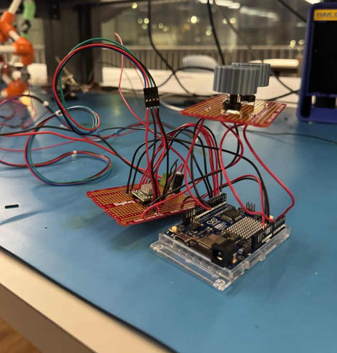
Electrical Design⌄
The electrical system provides the power and control signals needed to move the tilt actuators and spin the motors. I shared the responsibility of designing and integrating all electrical components with Ky-Anh Nguyen to ensure the system remained stable and responsive, even when the motors were running at full speed.
- Soldered & Heat-Shrunk
Every connection was soldered and used heat-shrink tubing for permanent, professional-grade durability.
- Strategic Routing
Wires were carefully organized and tied down to stay clear of the moving gears and tilting mounts.
- Manual Interface
We designed a control board with dual potentiometers, allowing us to manually adjust both thrust and tilt angle at the same time during testing.
- Dedicated Housing
We integrated a central protective case to keep the Arduino and battery safe from the mechanical movement of the modules.
Firmware Design⌄
I developed the C++ firmware that acts as the system's central logic, synchronizing mechanical tilt with motor thrust. The primary focus was maintaining high-precision control and system stability during the intense vibrations of active propulsion.
- Signal Processing
Implemented input filtering and smoothing to eliminate electrical noise, ensuring fluid motion and a positional accuracy of ±0.5°.
- Motion Profiling
Integrated slew rate limiting to govern transition speeds, protecting the 3D-printed gears from sudden mechanical stress.
- Vibration Stability
Developed deadband logic and software thresholds to keep the actuators stable and silent when no user input is detected.
- Power Optimization
Designed a motor-management routine that balances holding torque with heat reduction, keeping the mechanism locked during high-thrust maneuvers.
- Safety Constraints
Hardcoded operational limits to prevent over-rotation, protecting the internal wiring and mechanical stop-points.
